
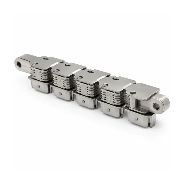
SFF-SS38.1 Stored Frozen Food Conveyor Chain
SFF-SS38.1 stored frozen food conveyor chain with inner-ring and outer-ring configurations, 38.10 mm pitch and verified shell/interface dimensions.
SFF-SS38.1 Stored Frozen Food Conveyor Chain: geometry first, application second
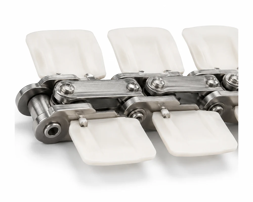
SFF-SS38.1 is a dedicated frozen-food conveyor chain configuration built around a 38.10 mm pitch and a shaped shell/interface rather than a generic roller chain attachment. The catalogue distinguishes inner-ring and outer-ring versions. Their core chain dimensions are the same, while the inner-ring row includes an accessory size that is not specified for the outer-ring row. That distinction should be preserved in a replacement order because the shell and accessory geometry determine how the conveyed product or carrier interfaces with the chain.
For buyers comparing alternatives, start with the verified dimensions below and then review the wider Food Conveyor Chains family. Verified dimensions are shown separately from verified catalogue dimensions from application questions that need confirmation on the RFQ.
For final release, keep the approved configuration, measured interface, quantity and application conditions together on the purchase record so receiving inspection and future repeat orders reference the same controlled basis.
Verified dimensions
Dimension key: P = pitch; L = pin length; d = pin diameter; D = roller diameter; h1+h2+h3 = catalogued plate geometry; b1 = width between inner plates; Lc = pin length; T/t = plate thickness; l×w = shell size.
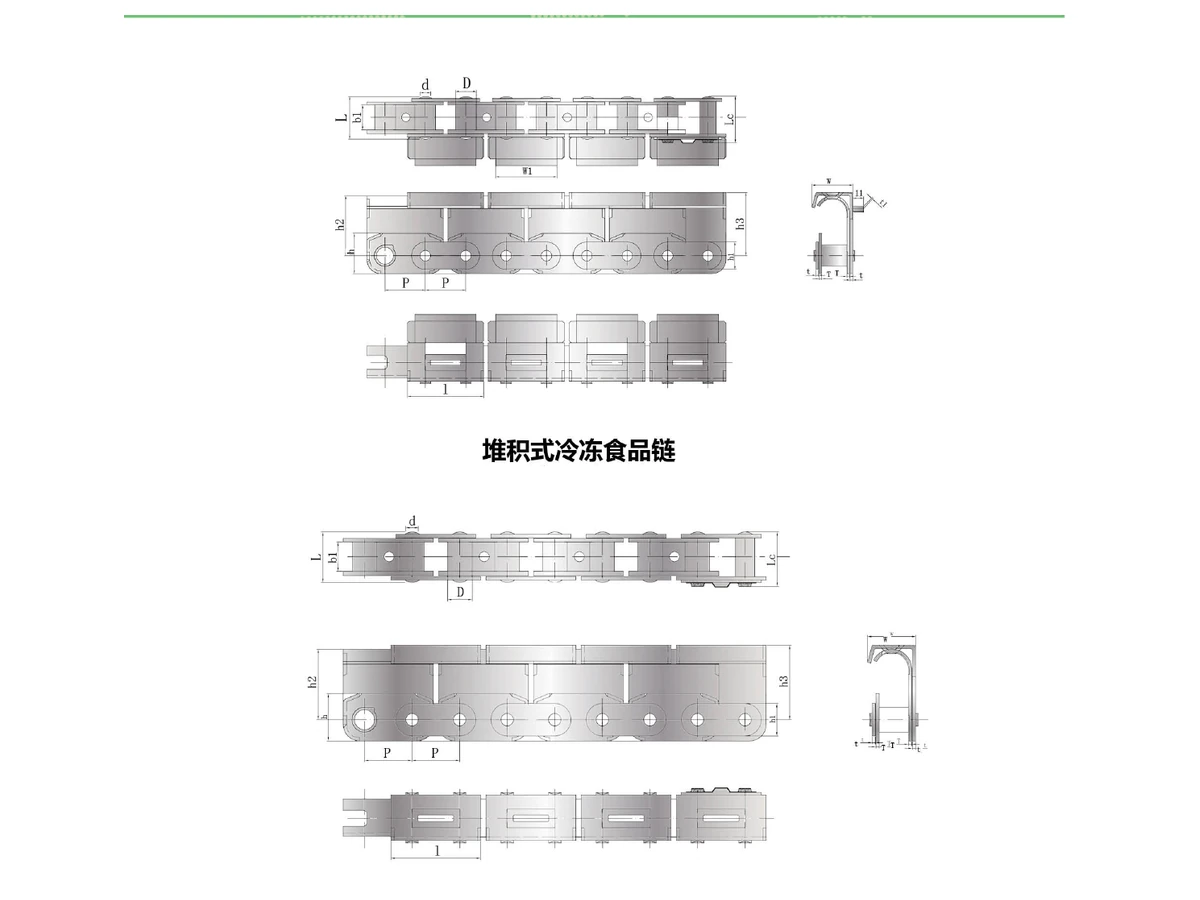
| Configuration | Pitch P (mm) | Pin Length L (mm) | Pin Diameter d (mm) | Roller Diameter D (mm) | Plate Geometry h1+h2+h3 (mm) | Inner Width b1 (mm) | Pin Length Lc (mm) | Plate Thickness T/t (mm) | Shell Size l×w (mm) | Accessory Size (mm) |
|---|---|---|---|---|---|---|---|---|---|---|
| SFF-SS38.1 Inner Ring | 38.10 | 40.00 | 10.00 | 20.00 | 38×26×56×59 | 23.50 | 47.00 | 2.5 | 72×38 | 11×59×1.5 |
| SFF-SS38.1 Outer Ring | 38.10 | 40.00 | 10.00 | 20.00 | 38×26×56×59 | 23.50 | 47.00 | 2.5 | 72×38 | — |
How to specify the right configuration
For replacement selection, identify whether the installed component is the inner-ring or outer-ring form and verify the 72×38 shell envelope along with the 38×26×56×59 plate geometry shown in the catalogue. Measure several pitches, confirm roller diameter and inner width, and photograph the chain from the top, side and end. Frozen environments can also change clearances through icing or product accumulation, so report any recurring contact marks or guide wear instead of assuming that a tighter fit is desirable.
Include conveyor speed, total loop length, product mass and spacing, start/stop pattern, curves or inclines, temperature zones, sanitation method and the existing drive or sprocket arrangement. These operating details are intentionally requested rather than converted into unsupported catalogue ratings.
Design around the machine interface
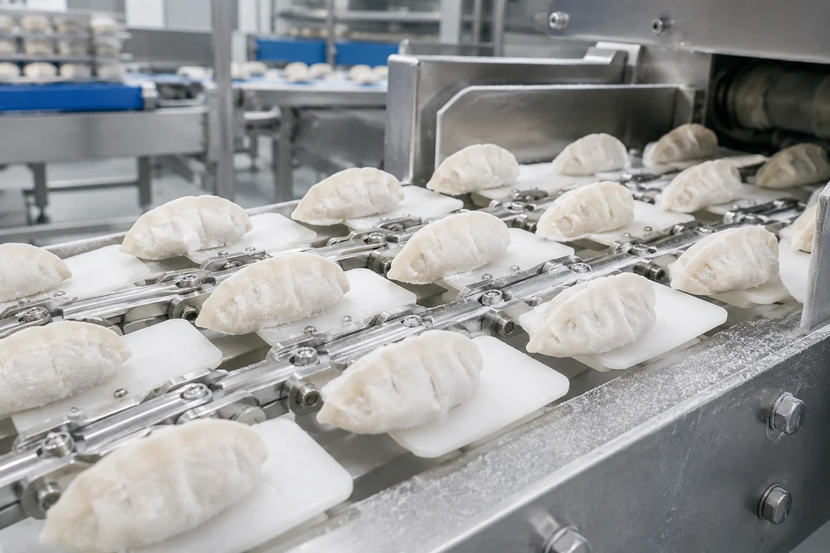
Before finalizing a replacement, compare the component with the complete conveyor path. Small differences in guides, transfer height or sprocket engagement can determine whether an otherwise similar chain or belt runs freely.
The visible conveying element is only one part of the system. Guide rails, sprockets, support tracks, transfer plates, tensioning and sanitation access all influence service life and product handling. When replacing an existing conveyor component, send the mating-interface dimensions instead of asking for a visual match alone.
For a broader project checklist, see our food conveyor chain selection guide.
Installation and commissioning checks
Install the chain on a clean, inspected guide path and rotate it through the entire system by hand or at the lowest safe speed. Watch the shaped shells through transfers and curves; a local interference point can damage both the carrier and chain. Confirm that sprocket teeth enter the roller/pitch geometry cleanly and that the inner/outer-ring interfaces face the intended direction. Re-check tension after the first controlled run because trapped frost or debris can give a false impression of correct take-up.
Keep geometry stable through sanitation and wear
Sanitation should remove food residue and ice without prying on the shells or forcing the chain sideways. After washdown and drying, inspect the shell edges, attachment junctions, pins and rollers. If the line experiences repeated freeze/thaw cycles, include that information in the RFQ so material, lubrication and clearance review can be based on the actual duty. The published catalogue dimensions describe geometry; they do not replace a machine-specific assessment of temperature, chemical exposure or food-contact requirements.
Inspection should compare a repeatable reference length rather than judging one joint by eye. Record the location of abnormal wear so it can be related to a specific guide, transfer or sprocket.

What to send for an accurate quotation
- Model or complete designation, if known.
- Required quantity and whether the request is sample, replacement or production supply.
- Measured pitch, key widths/diameters, attachment or mesh geometry and overall belt/chain width.
- Clear top, side, end and drive-interface photographs; include a scale reference.
- Operating speed, product/load description, temperature zones, cleaning method and environmental exposure.
- Sprocket or mating-component details and any drawing revision used by the machine builder.
Use the RFQ contact page to organize the information before submitting it through the global enquiry form in the footer.
Common engineering questions
What is the pitch of SFF-SS38.1?
The catalogue lists a 38.10 mm pitch for both the inner-ring and outer-ring configurations.
What changes between inner ring and outer ring?
The core listed chain dimensions are the same; the inner-ring row includes a catalogued accessory size of 11×59×1.5 mm, while the outer-ring row shows no accessory size.
Should shell size be measured?
Yes. The catalogued shell size is 72×38 mm and is important for matching the product-carrying interface.
Can a standard roller chain replace it?
Not as a direct assumption. The shaped shell/interface is part of the functional geometry and must be matched.
What should a frozen-line RFQ include?
Include configuration, quantity, photos, pitch, shell/interface dimensions, line speed, temperature range, cleaning method and sprocket information.
A practical way to avoid a visually similar but mechanically wrong replacement
A replacement can match pitch and still fail because the roller, inner width, attachment height, top-plate envelope or cross-machine interface is different. Build a compact measurement sheet before contacting suppliers. If the old component is worn, take measurements from several less-damaged areas and note which values are estimated. Never silently round a measured value to a familiar nominal size; keep the measured value and the proposed nominal value as separate fields until the match is confirmed.
The specification table above is catalogue evidence for the listed model or configuration. Conveyor speed, support spacing, curve radius, product temperature and cleaning chemistry belong to the machine application and must be confirmed for the project. Keeping these two data sets separate prevents a common procurement error: treating a catalogue geometry value as a performance guarantee for a different conveyor layout.
Before production quantity is released, compare the proposed chain or belt with the sprocket, guide and transfer geometry. A marked-up drawing or a first-article sample is more useful than a product photo when the machine has special guards, side rails or attachments. The goal is an interface that can be inspected objectively during incoming inspection and commissioning.
Keep SFF-SS38.1 Stored Frozen Food Conveyor Chain traceable from RFQ to incoming inspection
Before placing a production order, convert the agreed configuration into a short acceptance sheet. Put the exact model or designation at the top, followed by the dimensions that control fit on the machine. Attach the approved drawing or marked reference image and identify any dimension that was taken from a worn sample rather than a controlled source. This distinction is important because a supplier should not be asked to reproduce wear simply because the old part was the only sample available.
For repeat orders, keep the same stable item reference and note any deliberate revision. If a later machine modification changes a guide, sprocket, support rail or transfer, update the interface record rather than silently changing the chain or belt. This creates a useful history for procurement and maintenance teams and reduces the chance that two visually similar but mechanically different versions are mixed in stores.
Check the machine before blaming the replacement component
A conveyor component can show accelerated wear even when its manufacturing dimensions are correct. Inspect the mating sprocket, guide and transfer surfaces for burrs, hooks, steps, side pressure and localized contamination. Compare left and right sides of the machine and mark any position where the chain or belt changes direction. If the old component has a polished band or bent attachment that repeats at the same location, document that point before the old loop is removed.
After installation, create a controlled low-speed baseline. Listen for repeating noise, watch the same marked joint through the drive and return, and confirm that product transfer is stable before increasing speed. If the machine uses take-up adjustment, record its final position. A short baseline record makes later maintenance more objective because the team can compare current condition with the state immediately after commissioning.
These checks also help quotation quality. When the supplier receives clear evidence about fit, wear location and operating duty, the response can focus on the relevant geometry or process question instead of asking the buyer to choose from a long list of generic options.