Chain Driven Conveyor Belt
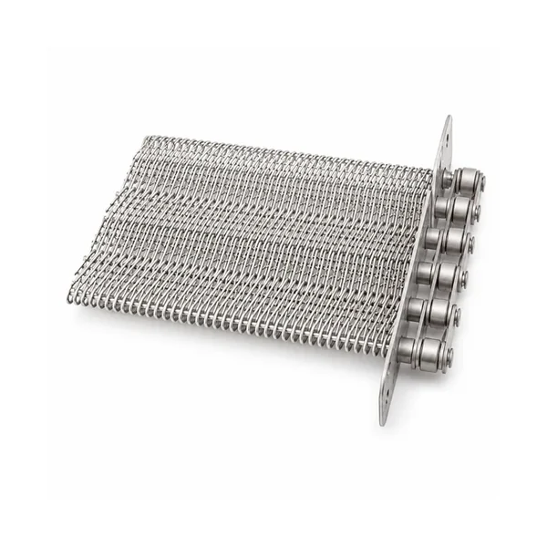
Chain driven wire conveyor belt configurations including stay pins, constant-thickness pins, large or triangular spirals, product stoppers and side guards.
Chain Driven Conveyor Belt
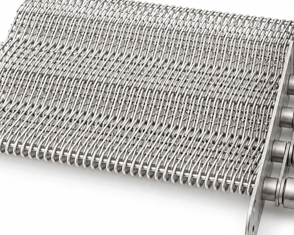
A chain driven belt combines an open wire-mesh conveying surface with positive drive at the belt edges. The series specification shows several construction options: K2 stay pin, stay pin, constant-thickness pin, large spiral, triangular spiral, angle product stopper and a version combining side guards with an angle stopper. These are functional construction choices rather than cosmetic variations. They affect how the belt is connected to the side chains, how products are supported and how product position is controlled on inclines or through process zones.
For replacement work, treat the wire-mesh body, side chains, cross connections and optional guards or stoppers as one interface. The part should be compared with the conveyor that exists today, including any guide, carrier or sprocket modifications made after the original machine was commissioned.
Check the features that control fit and motion
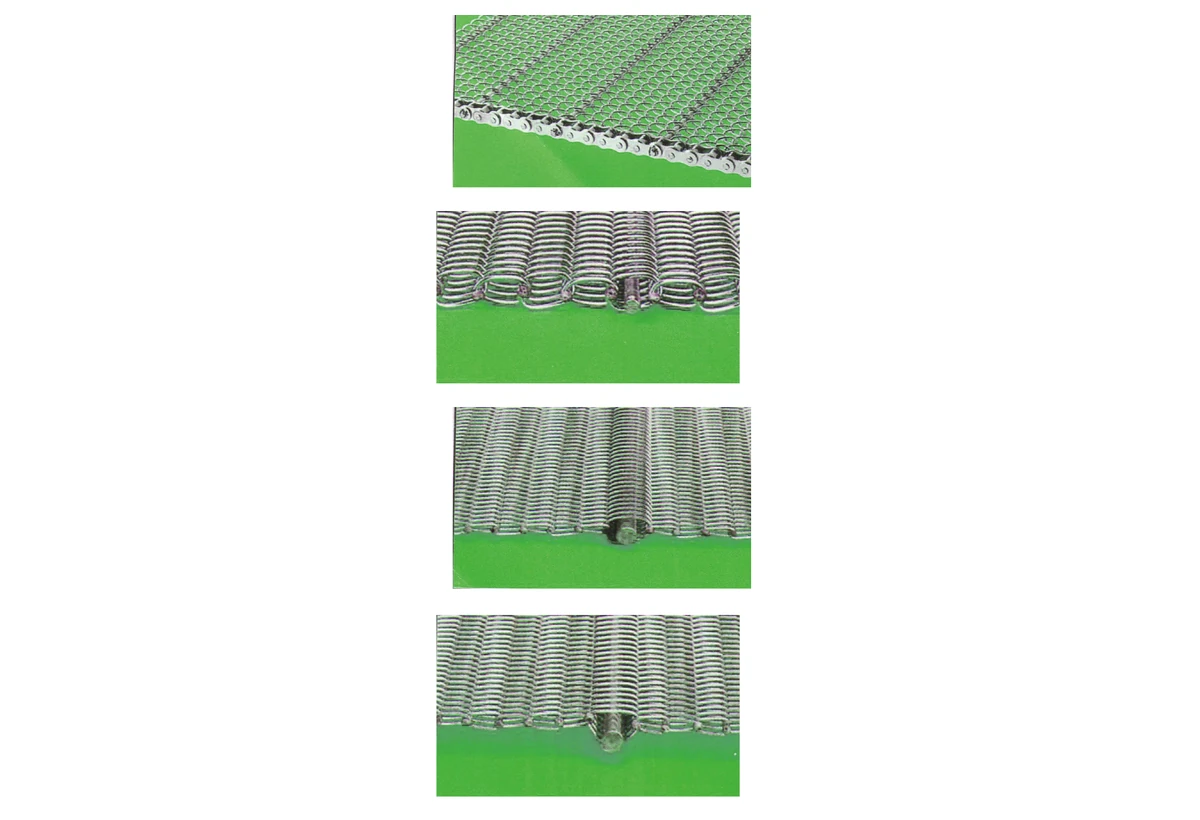
The key review points are chain synchronization, cross-machine alignment and mesh entry into the drive. Measure several repeating features where possible instead of relying on one worn joint, rod or attachment. Photograph the component while it is still installed so running direction, guide contact and drive engagement are visible.
No single universal dimensional table is listed for all of these variants. A precise RFQ should supply belt width, side-chain information, center-to-center distance between chains, mesh pitch or sample measurements, edge connection, product size and required stopper or guard geometry. Also describe the drive and return sprockets, conveyor path and any incline. Where the old belt is available, photographs from both top and underside plus a short physical sample can prevent an incorrect assumption about the stay-pin arrangement.
When dimensions are uncertain, label them as measured from a worn sample rather than rounding them into an assumed nominal value. This makes it easier to distinguish a true dimensional conflict from normal service wear during technical review.
Technical drawing and specification
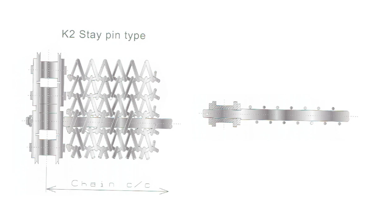
Configuration note: Available information lists configuration families rather than one universal dimensional table. Do not infer pitch, width, load or temperature from configuration images; provide the application geometry required for quotation.
| series specification Configuration | What to confirm on RFQ |
|---|---|
| K2 stay pin type | Stay-pin geometry, chain center distance, belt width and edge connection |
| Stay pin type | Pin form, spacing and mesh connection |
| Constant thickness pin type | Pin type and cross-machine engagement |
| With large spiral | Spiral form and product-support/open-area requirement |
| With triangular spiral | Triangular spiral geometry and product support |
| With angle product stopper | Stopper spacing, height, direction and product size |
| With side guard and angle product stopper | Side-guard height plus stopper geometry and spacing |
The table reproduces the available model/configuration data for this product page. Values not listed here should be confirmed from the project drawing, current component or machine interface rather than inferred from another series.
Evaluate the component inside the complete conveyor path
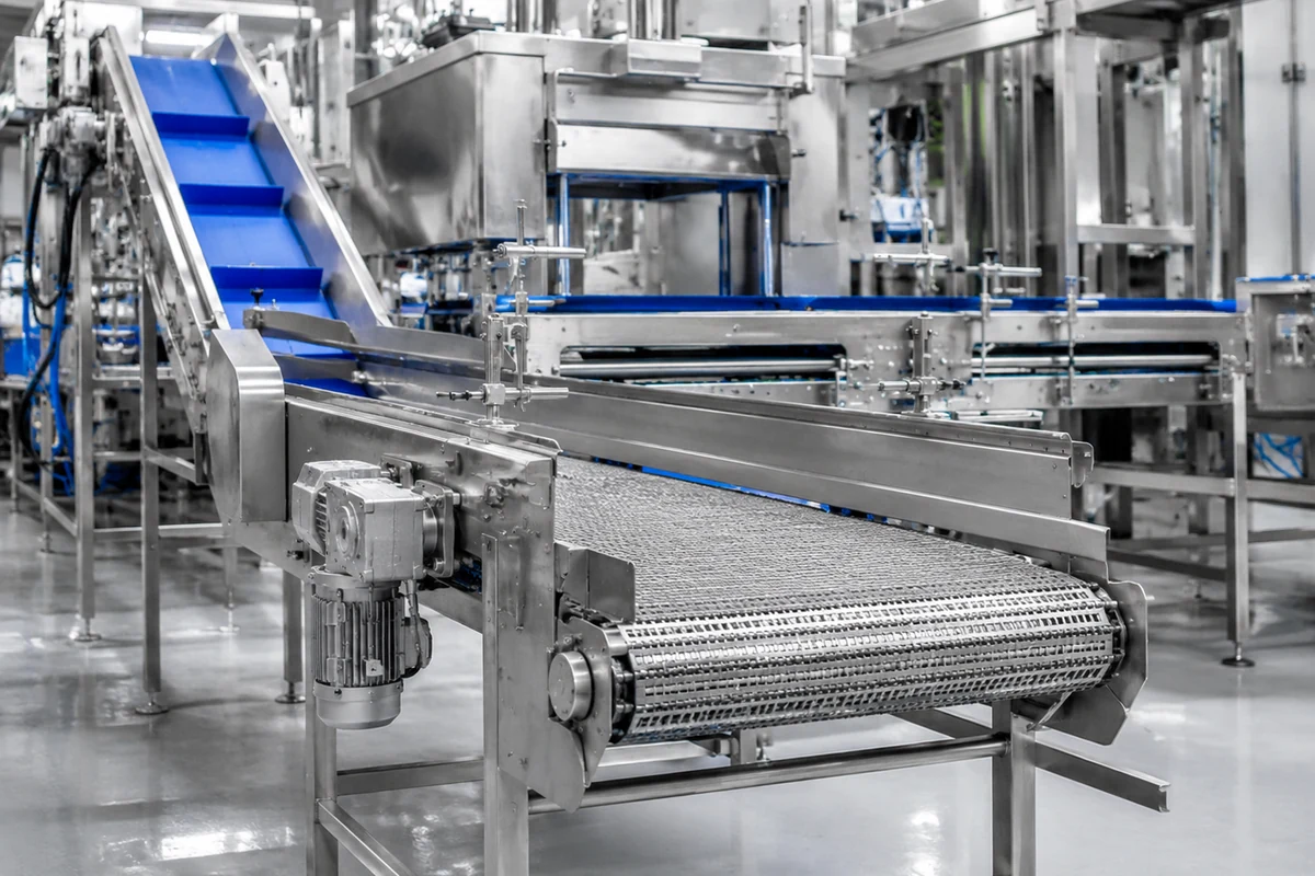
Chain Driven Conveyor Belt is considered for positive-drive food-processing conveyor systems. In addition to the component dimensions, state the product being conveyed, spacing, line speed, starts and stops, curve or incline conditions, process zones and sanitation method. These operating inputs help identify the interfaces that deserve extra attention during approval.
Inspect the drive, supports, transfer points and return path for wear or modification. If damage repeats at one machine position, correct that interface before judging a new chain or belt. A replacement component cannot compensate for a burr, misaligned guide, damaged sprocket or unsupported transfer.
Where the project is considering a different conveying architecture, compare the complete machine interface rather than making a visual substitution. A related reference on plastic conveyor belt alternatives can help frame the architecture comparison; final suitability still depends on the actual conveyor.
Commission at low speed before normal production
Install both side chains square to the shafts and verify that the wire mesh is not pulling one chain ahead of the other. Cross connections must stay aligned across the belt width. Run several empty revolutions and inspect the mesh where it enters the drive; positive drive should not force the mesh sideways or bunch the spirals. Product stoppers and guards require additional clearance checks at transfers and return paths.
After the initial empty run, compare the same observation points under representative load. Record any change in lateral position, articulation, transfer impact, noise or take-up position. A short, repeatable commissioning record makes it easier to separate normal bedding-in from a machine-interface problem that requires correction before routine production.
Clean and inspect sprockets, guides, supports and transfers before installing the new component.
Confirm running direction, lateral position and engagement without forcing the component into the track.
Follow a marked joint or belt row through the complete loop at the lowest practical speed.
Introduce representative loading and recheck transfer, curve, tracking and return-path behavior.
Keep the carrying surface and articulation points observable
Cleaning should address both the mesh and the side-chain joints. Remove residue from spirals, cross connections, stoppers and guards, then inspect for bent wire that can catch product. If the belt operates through heating or cooling equipment, state the actual temperature cycle and sanitation method in the RFQ because the configuration image does not establish a universal temperature or material rating for every configuration.
Record any recurring edge wear, polished guide contact, deformed attachment, pin movement, hook misalignment or mesh distortion. A dated photograph at the same inspection points makes trend changes easier to recognize than an isolated end-of-life inspection.
Freeze the dimensions and checks that matter for repeat orders
After the first acceptable sample or production batch is confirmed, retain the model/designation, current dimension record, approved photographs and the machine position where the component is used. For Chain Driven Conveyor Belt, include the features that control chain synchronization, cross-machine alignment and mesh entry into the drive. If the conveyor is modified later, update the interface record instead of assuming the historical part number still describes the machine.
For a new enquiry, keep each model as a separate technical line even if several models are combined commercially. State sample quantity and production quantity separately. If a particular material, surface condition or special process is mandatory, identify it as a requirement so it can be reviewed against process minimums.
Questions to close before production approval
Confirm wire-mesh body, side chains, cross connections and optional guards or stoppers against the current machine. Record where the part is supported, guided and driven, and identify any feature that has been repaired or modified.
Describe product footprint, spacing, orientation and transfer points for positive-drive food-processing conveyor systems. Note curves, inclines or hanging sections that change the clearance requirement.
Photograph recurring wear and identify the machine position where it occurs. Check chain synchronization, cross-machine alignment and mesh entry into the drive before deciding that the old component itself caused the problem.
For incoming inspection, select dimensions that can be measured consistently and tie them to the drawing or approved sample. Do not use appearance alone as the acceptance criterion when two configurations share a similar overall form. For commissioning, document the low-speed result before normal production so later maintenance has a baseline for comparison.
When ordering repeat quantities, state whether the machine, product format or cleaning process has changed since the previous batch. A small change to guides, transfers or product spacing can alter which interface controls performance even when the nominal component model remains the same.
Confirm Chain Driven Conveyor Belt against the current conveyor before production quantity
A dimensional table identifies the listed product, but replacement approval should also compare the wire mesh, side chains, stay pins and drive sprockets with the machine that will receive the part. For Chain Driven Conveyor Belt, record side-chain center distance, cross-machine alignment, mesh connection and stopper clearance using the same datums that will be used for incoming inspection. If an old component is worn, measure several repeats and photograph the least-damaged reference area rather than selecting one convenient value.
Photographs should show more than the loose component. Include the drive and return path, both conveyor edges, the tightest transition, and any location where wear repeats. Add one overall machine view so the running direction and product path are unambiguous. When a guide, sprocket, support or transfer has been repaired, note that change because the current as-built interface is the one the replacement must fit.
For sample approval, agree on the critical dimensions and visible configuration before the sample is produced. During low-speed testing, follow one marked joint, carrier or belt row through a complete revolution and note any rubbing, lift, skew, cyclic noise or product-position change. If the symptom appears at one fixed machine location, inspect the surrounding hardware before changing the component specification.
For repeat orders, retain the accepted model, dimension record and machine position together. This reduces ambiguity when the same facility uses similar components on several lines. If the product format, line layout or cleaning process changes, include that change in the next enquiry even when the component designation is unchanged.
Chain Driven Conveyor Belt FAQ
Does the series specification give one standard size for chain driven belts?
No. It presents construction types and application variants rather than a single universal dimensional table.
What is the main advantage of side chains?
They provide positive, synchronized edge drive when the belt and conveyor are designed as a matched system.
When are product stoppers useful?
They can help control product position on inclines or indexed transfer sections, but height and spacing must match the actual product.
What should be measured on an old belt?
Record belt width, side-chain pitch and center distance, mesh geometry, cross connection, edge details, stopper/guard dimensions and sprocket data.
Can a plastic modular belt be substituted?
That is a system-level redesign rather than a direct replacement. Compare drive, support, temperature, sanitation, airflow and transfer requirements before changing belt architecture.
Check measurable features before production release
Use reproducible dimensions and current machine photographs for incoming inspection and replacement approval.

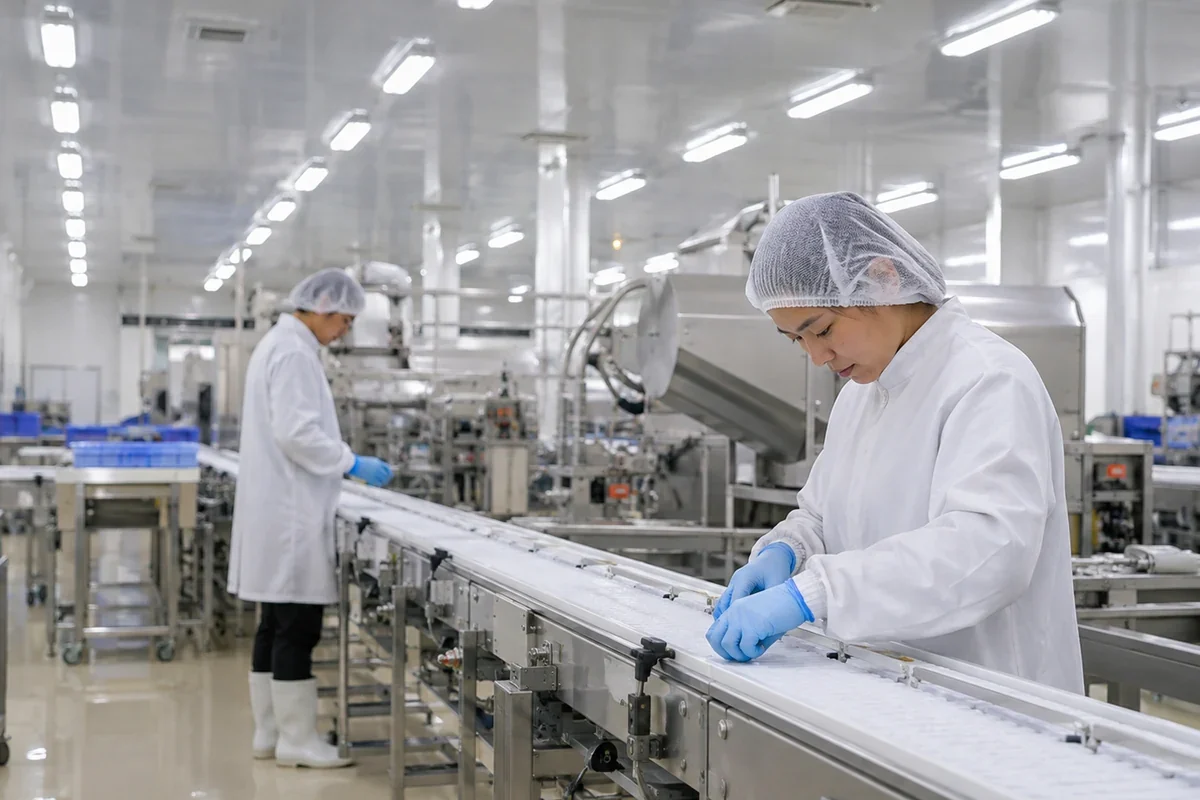
Include the current conveyor path and operating conditions when the project is a replacement or retrofit.